
Corvette Magnetic Ride Control is an electronically managed damping system. At each equipped shock absorber, a magnetic field changes the behavior of fluid containing magnetically responsive particles. A controller varies electrical current as the car moves, altering resistance to suspension motion. The result is a wide and rapidly adjustable range of damping without asking the driver to stop and turn a mechanical adjuster.
To place How Corvette Magnetic Ride Control Works in a wider ownership and engineering context, continue with A Real-World Corvette Maintenance Schedule.
That concise description matters because the feature is often credited with jobs it does not perform. It does not change the steel or composite spring rate, create tire grip, reset alignment, raise the car over a driveway, or repeal the limits of road surface and physics. It controls how quickly suspension movement is resisted. The complete Corvette chassis still depends on springs, anti-roll bars, bushings, tires, geometry, structure, steering, brakes, aerodynamics, and software.
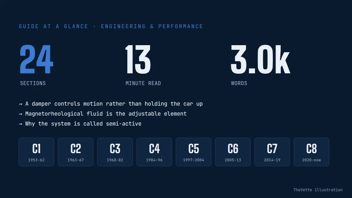
A damper controls motion rather than holding the car up
The road spring carries vehicle load and permits wheel travel. After a bump compresses a spring, stored energy would make the body and wheel oscillate if nothing controlled the motion. A shock absorber converts some suspension-motion energy into heat by forcing fluid through a restricted path. Engineers call this damping. Compression damping acts as the shock shortens; rebound damping acts as it extends.
More force is not automatically better. Excessive damping can prevent a wheel from following a rough surface and can transmit sharp motion into the body. Too little allows repeated float, pitch, roll, or wheel movement. Required force also changes with damper velocity: a slow body roll in a long corner is not the same event as a sharp pavement joint. A useful system must respond to direction, speed, vehicle state, and engineering targets rather than merely selecting “soft” or “hard.”
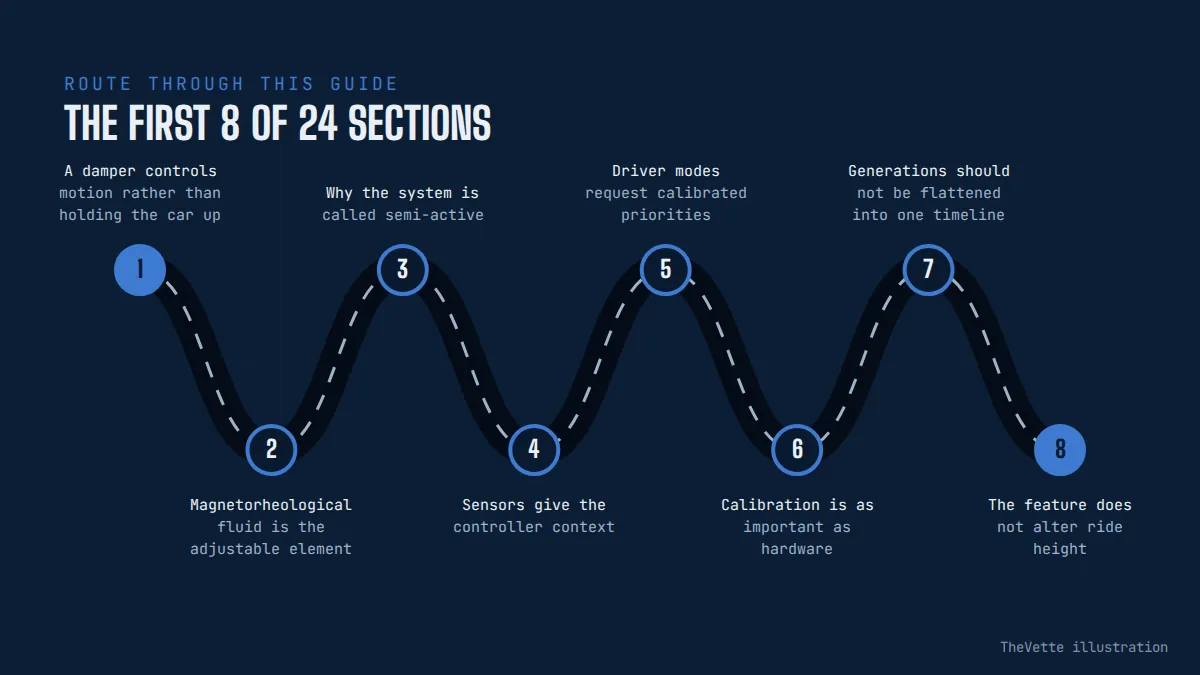
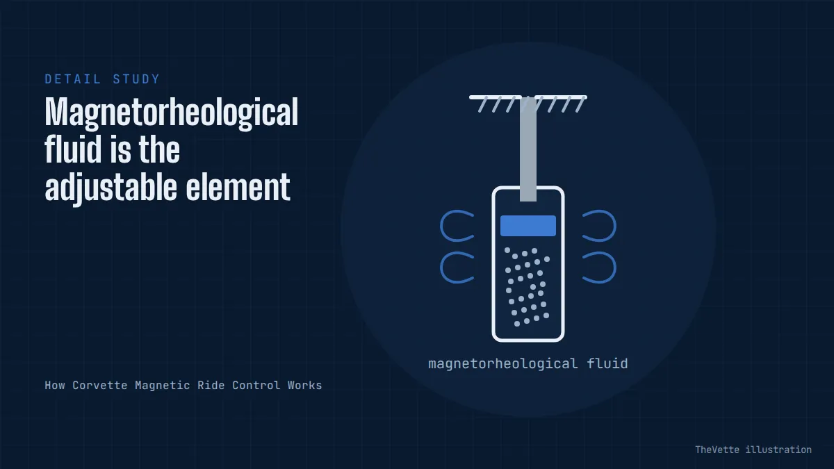
Magnetorheological fluid is the adjustable element
Inside an MR damper, microscopic magnetically responsive particles are suspended in a carrier fluid. With little commanded magnetic field, the fluid passes through the working region with relatively low resistance. Applying current to an electromagnetic coil creates a field that encourages particle structures to form along its lines. That raises the fluid's apparent resistance in the controlled passage and therefore changes damper force.
The fluid does not simply become a permanent solid, and the system does not rely on a conventional motor turning a needle valve for every adjustment. Current can be varied continuously within the designed operating range. SAE engineering descriptions model MR damper force as a nonlinear result of damper motion and command current. That is why the same electrical command cannot be translated into one universal “firmness” number independent of piston velocity, temperature, damper design, and calibration.
Why the system is called semi-active
A fully active suspension can use actuators to add energy and deliberately move the body or wheel. A passive shock dissipates motion according to fixed mechanical characteristics. Magnetic Ride Control sits between them: electronics can change the force relationship very quickly, but the damper remains fundamentally an energy-dissipating device. It cannot extend itself like a hydraulic lift or command the wheel through a pothole before suspension movement exists.
“Semi-active” is not an insult or a lesser marketing tier. It describes a useful safety characteristic: the controller chooses among available damping forces rather than powering the suspension in arbitrary directions. This provides substantial authority over ride and body control with less mass and energy demand than many fully active arrangements. The exact fail-safe behavior remains vehicle-specific and must be read from the appropriate service information.
Sensors give the controller context
An adaptive damper needs information beyond the driver's mode selection. Depending on generation and configuration, the chassis network can provide wheel or body motion signals, steering input, vehicle speed, braking, acceleration, yaw, and other state data. The controller uses validated signals and calibrated logic to determine a target current for each corner. Commands can differ across the car because the left-front wheel encountering a patch does not require the same response as every other wheel.
This network explains why diagnosis cannot stop at the shock absorber. A damaged position sensor, wiring problem, poor connector contact, implausible network message, voltage fault, or controller issue can affect system operation even when the damper is not leaking. Conversely, a stored chassis code does not prove the named component is mechanically defective. The code identifies a detected condition and a diagnostic path, not permission to replace the most expensive part.
Driver modes request calibrated priorities
Tour, Sport, Track, Weather, My Mode, or other labels describe vehicle-level strategies, and their availability changes by generation and model. A mode can coordinate throttle, transmission, steering, exhaust, electronic limited-slip differential, stability control, traction management, displays, and damping. Selecting Track therefore does not mean that every system merely moves to its maximum value.
Within the damping controller, a mode selects maps and targets developed for that chassis, tires, springs, mass, and performance mission. The controller continues responding moment by moment inside that framework. A Tour setting can add force during a major transient, while a performance setting can release force when wheel compliance is valuable. Treating modes as four fixed shock settings misses the adaptive part of the design.
Calibration is as important as hardware
Two Corvettes may use related MR technology yet behave differently because of spring rates, motion ratios, mass distribution, tires, aerodynamics, and control software. Chevrolet's C8 Z06 material, for example, identifies a specific Magnetic Ride Control calibration for the Z07 package alongside its track-oriented tires, aero, and chassis tuning. That combination cannot be recreated by copying only one calibration label to another car.
Calibration determines target forces, transitions, filtering, temperature compensation, diagnostic thresholds, and cooperation with other modules. Updates may address a defined production configuration, but an owner should not assume that newer software is universally compatible or that flashing a controller will transform one suspension package into another. Verify VIN applicability, hardware part numbers, service bulletins, and programming requirements through authorized information.
Generations should not be flattened into one timeline
Corvette offered electronically adjustable Selective Ride systems before the magnetorheological design arrived. Those earlier systems may use adjustable valves and different control methods. The presence of a console selector or a familiar option description does not prove that the shocks contain MR fluid. Parts catalogs, build codes, owner manuals, and service procedures must be matched to the exact year.
Magnetic Selective Ride Control became a recognizable Corvette option in the C5 era and evolved across C6, C7, and C8. Later “4.0” branding refers to a newer control generation, not four liters of fluid or four manually chosen positions. Avoid universal claims about sample rate, reaction time, sensor count, or internal construction unless an authoritative source documents the particular version.
The feature does not alter ride height
C8's available front-lift system and Magnetic Ride Control are distinct. Front lift uses separate hardware to raise the nose for low-speed obstacles and can include location memory. Magnetic dampers control motion throughout suspension travel but do not lengthen the spring or establish a taller static position. A car that sits unevenly needs ride-height, spring, tire, bushing, damage, loading, or lift-system diagnosis rather than a firmer damper mode.
Lowering collars, springs, or aftermarket components can change available bump and rebound travel. Even if the electronic shock remains connected, operating it outside intended position or velocity ranges can compromise ride, handling, clearance, and durability. Alignment must be checked after geometry changes. Electronic adaptability cannot restore travel removed by an unsuitable physical setup.
Tires remain the only contact with the road
Adaptive damping can help keep tire load better controlled during transients, but it cannot make a cold summer tire grip like a suitable tire at operating temperature. Inflation, age, compound, tread, construction, damage, temperature, and road contamination set fundamental boundaries. Run-flat and non-run-flat changes also affect response because the tire sidewall participates in the suspension.
When a car begins to feel harsh, nervous, or vague, record tire model, size, pressure when cold, age code, wear, and ambient conditions before blaming electronics. Mixed tires or incorrect sizes can also disrupt chassis expectations. Follow the door label and model-specific manual, then adjust for documented track guidance only when the conditions and procedure apply.
Springs and anti-roll bars define another layer
A higher spring rate resists displacement for a given load. An anti-roll bar couples left and right suspension movement and influences roll stiffness distribution. Dampers influence the rate of the transition, especially while the car enters or leaves a maneuver, but cannot supply permanent steady-state spring force in the same way. This distinction explains why a track package can combine different springs with different MR calibration.
Installing stiffer springs and asking the controller to “soften them” has limits. Ride frequency, travel, bump-stop engagement, tire load, alignment change, and damper velocity all move. A coherent package must consider the whole operating envelope. Preserve exact part numbers and baseline measurements so an undesirable result can be understood and reversed.
Alignment can masquerade as a damping complaint
Toe strongly affects stability and tire wear; camber influences contact geometry in corners; caster and compliance affect steering behavior. An impact, curb strike, worn joint, incorrect ride height, or careless adjustment can make a Corvette wander or react sharply even with healthy dampers. Track-oriented alignment may trade street tire life and straight-line calm for cornering behavior.
Request a printed before-and-after alignment report with the correct model and package specification. Inspect tires, wheels, bearings, ball joints, tie rods, bushings, and fasteners. Do not use a mode-button comparison as the sole chassis test when mechanical geometry is unknown.
What a healthy system may feel like
On a consistent road at a legal speed, changing damping priorities may alter body settling after a crest, pitch during braking, roll build-up, steering response, and the sharpness of impacts. Differences can be subtle on smooth pavement because little suspension motion needs control. Temperature, tires, load, roof configuration, road wavelength, and driver input can overwhelm a casual comparison.
A dramatic clunk, repeated bounce, pulling, grinding, or warning message is not evidence that the system is simply in the wrong mode. Stop if control is compromised, a tire is damaged, fluid is escaping, or a suspension component may be loose. A safe inspection is more valuable than repeatedly driving over a bad road to amplify a symptom.
Leaks deserve a clean, careful inspection
A light film and an active fluid leak are not necessarily the same condition, and dirt can make their boundary difficult to see. Clean only as the service procedure permits, inspect the shock body, shaft area, electrical connector, mount, nearby lift hardware, brake lines, and surrounding components, then document whether fresh wetness returns. Fluid reaching a tire or brake requires immediate attention.
Do not open, drill, heat, or attempt to refill a sealed MR damper. The fluid, gas pressure, seals, piston, electromagnetic assembly, and manufacturing fill are an engineered unit. Replacement decisions should use service criteria, not an online photograph from an unrelated model.
Noise can travel through the structure
A knock attributed to a shock may originate in an upper or lower mount, stabilizer link, control-arm joint, spring seat, brake component, wheel, undertray, cargo item, roof panel, or body attachment. Sound location from the cabin can be misleading. Reproducing the noise safely while a technician uses chassis microphones or controlled loading can separate sources.
Record whether it occurs on single-wheel bumps, both-wheel heave, braking, steering, temperature change, or a particular mode. Inspect torque and witness marks using approved procedures; do not tighten suspension fasteners randomly while the vehicle hangs, because some bonded bushings require a specified ride-height position.
Electrical diagnosis starts with evidence
A capable scan tool should read the appropriate suspension module, not only generic powertrain emissions codes. Save current and history codes, status, freeze-frame or failure records, voltage, and relevant data before clearing anything. Check battery condition and charging because low voltage can create misleading module behavior. Inspect connectors for impact, water, corrosion, pin damage, strained routing, and previous repair.
Service tests may command dampers or evaluate circuit current and resistance. Follow the exact procedure and meter limitations; indiscriminate probing can spread terminals or damage a controller. Never apply battery power directly to a damper coil unless official instructions explicitly specify the circuit and method. Successful resistance measurement alone also cannot prove correct hydraulic performance.
A warning message may change vehicle behavior
Owner manuals describe model-specific messages and restrictions when Selective Ride Control detects a fault. A C7 manual, for example, warns that speed may be limited when the system has failed and directs service. The precise message, allowed operation, and fallback vary, so paraphrasing one year as a universal rule would be unsafe.
Photograph the message, note speed and conditions, and avoid clearing it before diagnosis. If the car limits speed, feels uncontrolled, has contact between tire and body, or shows damage, arrange transport rather than testing the limit. Check the current owner manual and service information for the VIN.
Replacement shocks require exact identification
Order by VIN, year, model, suspension option, axle and side where applicable, not merely “C7 magnetic shock” or “C8 front.” Connectors, valving range, mounts, lift compatibility, calibration, and revisions can differ. Confirm whether associated nuts, bolts, mounts, retainers, or seals are single-use or separately required. Counterfeit or untraceable components create safety and calibration risk.
After installation, the car may require a trim-height check, alignment, diagnostic reset, learn procedure, programming, or road validation. Torque fasteners at the specified position and sequence. Route wiring with factory clips and clearance from tires, heat, and moving joints. Retain invoices and removed part numbers for future diagnosis.
Replacing in pairs is a decision, not a slogan
Balanced age and response across an axle can support consistent behavior, which is why pair replacement is commonly considered. Yet the correct decision depends on failure type, mileage, physical condition, part revisions, warranty, service policy, and measured performance. Four-shock replacement should not be sold automatically when one damaged connector has a documented repair.
Ask the technician to identify the failed test, not just the recommended bundle. Inspect the opposite corner and compare history. If mixed revisions are permitted, document them; if a service publication requires a set, follow it. Price should include necessary programming, alignment, hardware, and validation so competing quotes describe the same work.
Passive conversion changes the engineered system
Aftermarket kits can replace electronic dampers with passive units and may use modules or resistors intended to suppress warnings. Eliminating a message does not reproduce the original force control or prove that stability-related systems receive valid behavior. Ride and handling then depend on the fixed dampers and their match to springs, tires, mass, and intended use.
A conversion may be chosen for budget or competition reasons, but it should be evaluated honestly. Confirm road legality, inspection requirements, insurance disclosure, warning behavior, thermal safety of electrical devices, and compatibility with other controls. Keep the original harness undamaged where possible and disclose the modification to a buyer. Never advertise a converted car as retaining functioning Magnetic Ride Control.
Aftermarket controllers demand validation
A replacement or add-on controller can alter current commands, but advertised percentages do not necessarily equal an OEM mode. Safe validation needs correct electrical limits, fault handling, temperature behavior, sensor interpretation, latency, and a force model for the exact dampers. A pleasant street impression does not establish performance during emergency avoidance or sustained track heat.
Use suppliers that document applications, reversibility, diagnostics, software versions, and support. Save the original calibration and baseline scan. Test progressively in a controlled environment with tire pressures, alignment, load, temperature, and settings recorded. Public roads are not suitable for limit-handling experiments.
Track preparation includes more than choosing Track
The track setting is one element of preparation. Follow the exact manual or track guide for brake fluid, pads, wheel torque, tire pressure, alignment, cooling, oil, fuel, aero configuration, break-in, and post-session inspection. Requirements differ among Stingray, Z06, ZR1, packages, years, and tires. A mode selection cannot compensate for overheated fluid or loose hardware.
Build speed gradually with qualified instruction. Monitor messages, temperatures, pressure, tire condition, and handling consistency. If the car develops bounce, steering change, leakage, or a suspension fault, end the session and inspect it. Record setup and lap conditions so a change in damping is not confused with fuel burn, tire heating, or weather.
How to evaluate an equipped used Corvette
Decode the VIN and build data to verify that the feature is present and determine the suspension package. Check the owner manual, option label or official build record, and part numbers. A dashboard menu alone is weak evidence after years of module swaps or modifications. Inspect all four dampers, connectors, harnesses, mounts, lift hardware, wheels, tires, and underbody for leaks, impact, corrosion, and improvised repairs.
Scan every chassis module before the test drive and retain a report. Drive on a safe repeatable route, reaching normal temperature while comparing permitted modes without exceeding legal limits. Look for warnings, repeated oscillation, harsh impacts, noises, pulling, and inconsistent response. A specialist pre-purchase inspection is especially valuable on modified or track-used cars.
Service records make adaptive hardware easier to value
A strong file identifies replaced corners, dates, mileage, part numbers, software work, alignment values, tires, suspension modifications, and diagnostic codes. “New shocks” without manufacturer or invoice may conceal passive conversion or unsuitable parts. Receipts also help establish whether a repair remains under warranty.
For sellers, disclose current warnings and every electronic or mechanical change. For buyers, budget using VIN-correct part prices and complete labor rather than the cheapest search result. Magnetic Ride Control can be a meaningful feature, but neglected tires and geometry can erase much of its benefit.
The engineering advantage is controlled compromise
A fixed damper must balance comfort, wheel control, and transient body motion across many roads. Magnetorheological damping lets Corvette engineers move that balance while the car is operating and coordinate it with a selected vehicle strategy. It can remain compliant over small irregularities, add control during major inputs, and support model-specific performance tuning without requiring a manually rebuilt shock for each trip.
Its authority still has boundaries. Springs carry load, tires generate force, geometry guides the wheels, and the driver must respect conditions. Understanding those divisions leads to better diagnosis and fewer expensive guesses. Verify the precise Corvette configuration, preserve scan evidence, use authoritative procedures, and treat the adaptive damper as one well-integrated part of the chassis—not a magic substitute for the rest of it.